Tuesday, 25 Jan 2011 [59966 miles]
Brake caliper handing
Rear wheel removed
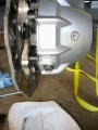
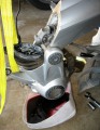
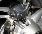
Clean around ABS sensor
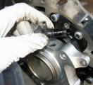
ABS sensor removed
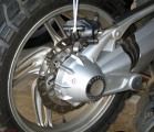
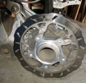
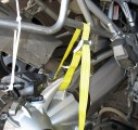
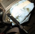
Yesterday, I left the rear brake caliper hanging from the pannier rack with some cable ties as I cleaned up. Today I started off by removing the rear wheel, cleaning around the ABS/speedo sensor, then removing the sensor in preparation for an FD fluid change.
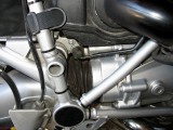
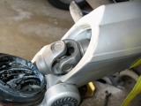
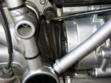
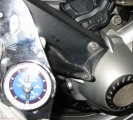
FD support
Loosen drain
Lower FD
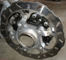
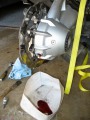
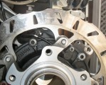
Last time I lowered the FD I didn’t have it strapped and paid the price in the form of a set of new rear brake pads to replace the one contaminated by splashing gear oil. This time I used a strap, loosening it a little at a time to lower the drive slowly, making sure the brake rotor didn’t wind up inside my fluid catch basin.
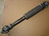
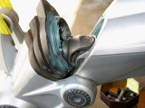
Drive shaft back
Lowered FD
Clipped
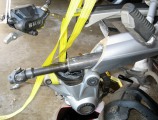
Drive shaft
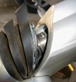
As the FD lowered and the boot unclipped itself I noticed that the drive shaft pulled back more than normal. I think it unclipped itself from the front (transmission) splines before the FD pinion splines came free. Not a big deal as the next step is to remove the drive shaft to take a look at the front U-joint. The drive shaft, a one-piece unit, slides out of the swing-arm.
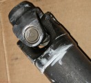
Front U-joint OK
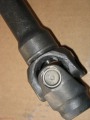
Rear U-joint OK
Cush OK
Ready for lube
That’s the drive shaft up close. U-joints look and feel good. I cleaned and greased the female splines. I also cleaned and put a light coat of grease on the pinion splines. An attempted wiggle of the pinion showed no more movement than normal. Time to put it back together.
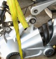
Put drive shaft back
Boot tie
Putting the drive shaft back was an interesting experience. I probably spent 30 minutes trying various things that all involved trying to look at the forward end of the drive shaft. The boot doesn’t open far enough to make that realistic.
Once I realized that I stuck a couple of fingers in the opening and aligned the forward splines with the transmission by feel. That took maybe 2 minutes of fiddling around getting the yoke in the proper orientation to control the vertical position from the rear of the bike.
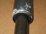
Keep water out
FD re-attach
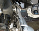
Forgot the washer
I ran out of white lithium grease so used whatever was at hand around the boot to keep water away from the U-joint. The strap helped support the FD until I inserted the bolt and grabbed a new lock nut. Oops. I noticed that I forgot the washer when I looked at the picture. Yep, there it was next to the used nut. I loosened the nut, installed the washer, and re-torqued the nut.
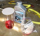
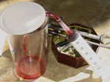
180 CC
Ready for clean-up
ABS sensor installed
Rear wheel installed
I installed 180 CC of gear oil through the ABS/speedo sensor opening using a syringe. The ABS sensor and drain plug O-rings were in excellent condition so I re-used them. I put the brake caliper and wheel back on the bike.
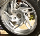
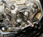
Caliper and mud guard support
8 Nm
Battery charged
The mudguard finishes up work on the rear of the bike. While the FD and drive shaft were being worked on the battery was on the charger. It shows a full charge after a short period of time. Guess the battery is still good. Should be, it’s only 6 months or so old.
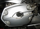
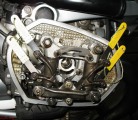
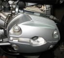
Disconnect coil
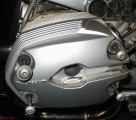
Coil removed
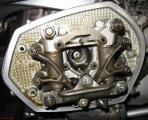
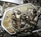
Valve cover removed
Spark plug tool
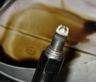
Plug OK
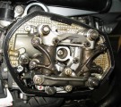
Time to adjust valves. The valve covers have to come off and the main spark plugs removed so I can bump the engine into position from the rear wheel. The same thing was done on left and right sides.
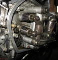
Right side first
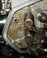
All 4 were tight
The rocker end play on 3 of 4 rockers is less than 0.10 mm. The 4th rocker is less than 0.15 mm. I’ll not bother doing any adjustments. All four valves on both sides were slightly tight. I adjusted the right side, then bumped the engine to work on the left. When done I started to button up the right side of the bike.
Return spark plug
Clean
Dry
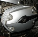
Valve cover installed
Coil installed
Left side needs love
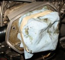
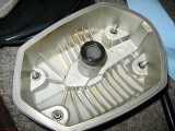
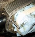
Protect the valve train
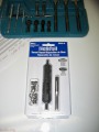
M6x1 kit
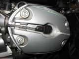
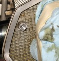
The left side of the bike needs some care. The first three years I owned the bike it was dealer serviced. Looking at the marks on the cylinder head where the valve cover screws deformed the metal tells me that at least once someone used quite a bit more torque than necessary. The last few threads in one of the mounting screw threaded holes finally gave way. Helicoil time.
tap
Tapped hole
Installing coil
Drill, tap, install coil. That was easy. Did you you notice the missing step? When I first tried to put the cover on the mounting screw going into the fixed hole seemed to bottom out before it was fully seated. Doh! I forgot to break off the tang at the bottom of the helicoil! Fixed.
Tight, again
All nice and tight again. Tomorrow I’ll put the crash bars back on and take a test ride to get the engine oil and trasmission fluid up to temperature before changing. I’ll also check throttle body adjustments with the engine warm. That should pretty much finish the service.