Monday, Aug 2, 2010 [19326 miles]
Ready to lift engine
Tilted forward
I used my scissor jack to take the load off of the mounting rods so I could pull the rear rod and tilt the engine up in preparation for installing the transmission.
Lube those splines
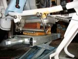
Transmission in place
Mounting screws
After installing a thin coat of moly lube to the transmission input splines I slid the transmission int the frame from the left side of the bike and positioned it so it was hanging from the mounting studs on the engine block. I used the kickstart lever to rotate the input shaft to get the splines to align with the clutch plate. The mounting hardware is only finger tight at this point.
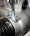
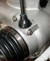
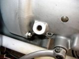
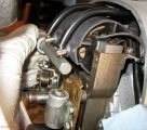
Rear engine mount
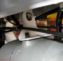
Top engine mount
Hardware attached
Next the engine was lowered so the bottom rear mounting bolt could be inserted. After some cleaning and polishing I installed the top engine mount with its hardware and a new cotter pin for the castle nut.
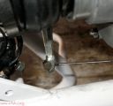
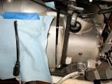
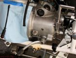
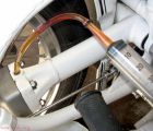
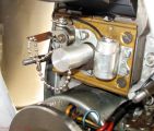
Clutch cable
Drive shaft
I installed the clutch cable, then hooked up the drive shaft. I then used the clutch while depressing the kickstart lever to rotate the transmission input and center the clutch on the transmission. Finally I tightened the transmission mounting hardware.
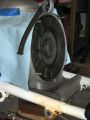
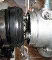
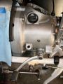
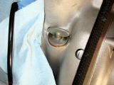
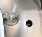
Keep water out
Boot is a pain
Getting the speedo cable to seat all the way and installing the boot took much longer than expected. The boot is quite hard and doesn’t want to stretch over the lip on the transmission housing. I used some grease to seal cracks where water might enter the transmission.
Drive shaft gear oil
Transmission gear oil
Now full
The drive shaft was drained of its remaining gear oil and new oil added. I also filled the transmission up as some gear oil was lost when I had the transmission on its side when replacing the input seal.
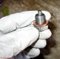
New crush ring
Engine Full
As long as I was playing with oil I put a new crush washer on the oil pan drain plug and filled the crankcase. Now I won’t have to worry about forgetting, later!
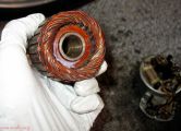
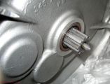
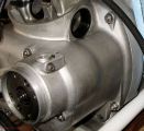
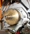
Clean rotor
Rotor installed
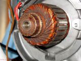
Generator installed
I used denatured alcohol to clean the generator rotor and the nose of the crank before installing rotor and generator. Not pictured was wiring up the generator and installing the vibration damper.
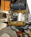
S mark
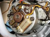
Magneto rotor, mark UP
Magneto body
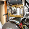
Magneto body
The magneto rotor and nose of the camshaft got the same alcohol wipe as the generator. Before installing the rotor I put the flywheel at the S mark and then loosely put the magneto rotor on the camshaft with the mark UP. After slipping the magneto body over the rotor and tightening it down I made sure the mark on the magneto was in the notch of the points plate.
Safety gap
Ready to time
I used a 10 mm allen to check that the safety gap was large enough. There was about a mm of gap, putting the total at 11 mm. Good.
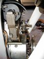
Point gap
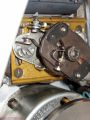
Static timing done
I set the point gap then got out the meter to set the static timing. I use continuity mode so it beeps at me when the points are closed, stopping just as the points open. They open close to the S mark. I’ll fine tune the timing once the bike is running with a timing light.
That’s all for today. Everything is done but the top end. Tomorrow I’ll see if I can get pistons and rings installed, cylinders honed and installed, and maybe the heads, too. Getting close to done.