2000 February 4 (Friday)
Paul noticed that I hadn’t updated the web pages for a while and wondered what was going on. I mentioned that the crank was installed and I was just about ready to put the block in the frame. He volunteered to help and I agreed - a second pair of hands would help minimize the damage done to the frame :-)
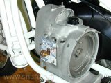
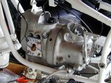
Timing case cover
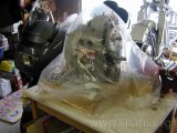
Engine under plastic
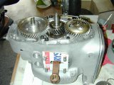
Timing bearing installed
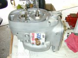
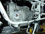
Timing case cover installed
Before we could put the block in the frame I needed to install the timing gear cover. The engine had been sitting under plastic since I got back from Joe’s almost 3 weeks ago. I removed the block from the stand and laid it on the bench with its nose pointing up. I then slightly heated the bearing and dropped it on top of the timing gear.
I placed the breather on the cam gear with shim and spring washer and oiled the face of the breather. While the bearing was still cooling I put some Hylomar on the gasket, and then heated the cover (taking care not to hurt the seals) and then dropped it over the timing gears. It went on easy. The cover was torqued down with a dab of Hylomar on the bolts that go all the way through the case.
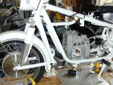
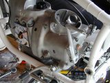
Installing engine in frame
Engine in frame (front)
Engine if frame (rear)
With two of us it was pretty easy to get the engine block into the frame, although we had to play with the mounts twice to get the side-stand (which takes the place of the spacers) just right. Hint: do the front first.
Top engine mount
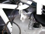
Top engine mount
Ok, we had to pull the front mounting bolt out again to get the part of the top engine mount that attaches to the block attached. This picture shows the final assembly of the top mount using the replacement SS hardware.
Clutch
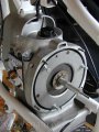
Clutch centering tool
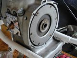
Clutch pressure plate installed
After abuse of a drill, vice, file, and sandpaper to do some needed tweaks to the clutch alignment tool, the clutch was installed. The first picture shows the alignment tool in use and the first three clutch screws installed. The clutch and pressure plate surface were roughed up a bit using some 100 grit sand paper.
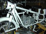
Transmission installed
Transmission in frame
Transmission attached
We pulled the swing arm out of the way and installed the transmission. Again, SS mounting hardware was used. This included replacing the nuts holding the rear cover of the transmission. The clutch/input splines were lubed with BMW #10 because I didn’t know any better.
Driveshaft
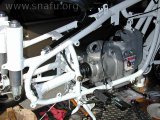
Drive shaft attached
Engine and transmission in frame
After double checking that the drive shaft coupling nut was torqued correctly, the drive shaft was re-installed and centered. That’s really all I’ve time for today. Will do more later.
Side stand
Side stand
This is a close up of the SS side stand. It looks quite sturdy as well as being pretty.